 Sign in
 Anonymous
on October 26th 2010
0
Anonymous
on October 26th 2010
0
Thanks
 | How to make a speaker icon from 3D model?September 27th 2005 |
This is a detailed tutorial on making an icon of a speaker in RealWorld Icon Editor. It covers all necessary steps, including creating a rough 3D model of a speaker, preparing a scene for rendering, and generating icon.
This guide is intended for people with basic knowledge about RealWorld Icon Editor.

If you follow the steps exactly, you will create this icon.
There are three basic icon creation methods:
Icons are created by manipulating pixels one by one, or by using a simple drawing tool such as line, floodfill, circle, etc. Changes are immediately applied, that means an already drawn shape cannot be easily modified. This method is suitable when creating simple icons, but it is used very rarely by professional icon designers.
A vector image consists from basic geometrical shapes (lines, ellipses, text, etc.) with applied effects. The shapes remain independent entities and author can modify their properties at any time. This method offers greater flexibility and allows fine-tuning the icons by modifying parts of the vector image. There are no problems rendering a vector drawing to a raster image of any resolution/size.
The advantages of vector images apply also to 3D models - they can be scaled and their parts can be adjusted at any time. Additionally, lighting, perspective transformations, and viewpoint can be changed freely. Of course, creating a 3D model requires more knowledge and adequate software.
...so, why should you bother creating a 3D model? To put it straight, it saves time...
When creating 3D models for icons, focus on simplicity. There is no point in having accurate and detailed 3D model, because icons are small and the details would not be visible anyway. Our model will be as simple as possible and will be made of four parts as shown on following picture.
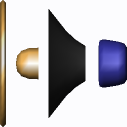
The models of a speaker consists of four simple parts - four surfaces of revolution.
Creating the speaker model is a matter of few minutes. Launch RealWolrd Icon Editor and create new document using "New Unicorn3D document" prototype. The new document is empty.
Let's start with the easiest part - the edge of the speaker. Insert new torus by clicking on the 'Insert Component' toolbar button and selecting 'Torus'. Rotate your view using your right mouse button (press the right mouse button in 3D view and move the mouse; release the mouse button when finished).
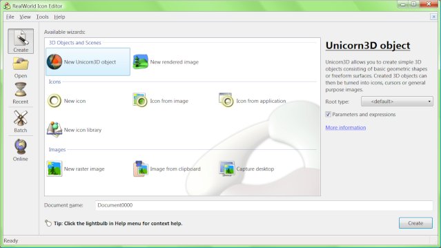 Create new Unicorn3D document by selecting 'New Unicorn3D document' and clicking the 'Create' button. | 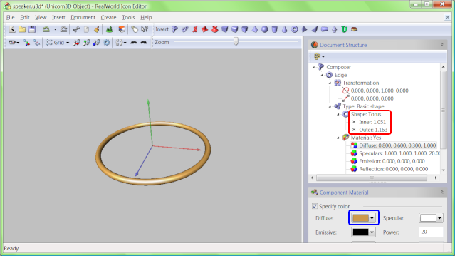 Torus was added to the 3D model using 'Insert component' command. 3D view can be rotated using right mouse button and zoomed using mouse wheel. |
Adjust the object's size and the material color according to the picture. If you want to create exactly the same speaker as on the picture, you can copy the numbers from the screenshot and type them in the tree view. Click on the screenshot to view it in full size.
Modify torus material in the Material panel  and set the inner an outer radius using control points or overwrite values in tree view
  .
.
Next, we will create the central part of the speaker. Insert a Surface of Revolution, change the material (same as above) and move the control points or copy the coordinates manually. It is a good habit to name the parts of a 3D model, click the 'Unnamed Component' item in the tree and change the text.
Tip: click on an object in 3D view and its control points appear; use mouse wheel to zoom in and out in 3D view.
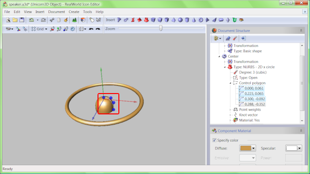 Change the material color to the same color as in the previous step and drag the control points to adjust the surface shape. | 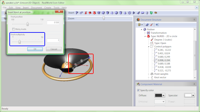 Select one of the control points in 3D view and the corresponding item is selected in tree view. Click on the toolbar button named 'Insert knot...'. |
After that, create the main part of the speaker. Insert another surface of revolution. Then click it in 3D view (its control points appear) and click on one of the control points (the tree view is synchronized). Click on the 'Insert knot...' toolbar button (a dialog appears). In the dialog, set knot multiplicity to 3 and press OK. Inserting knots into a NURBS curve increases the number of control points and allows us to create more complex surfaces.
Set the color of material to 0.2, 0.2, 0.2 and move the control points to proper positions in 3D view or type the exact value in tree view.
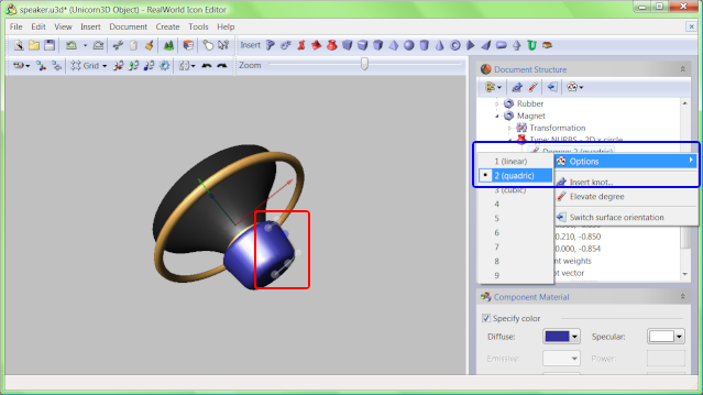
The last part of the speaker is also created from a surface of revolution. Insert one more and set its degree to 2. To set a degree, expand the tree and locate the degree item. Right-click on it an select 2 from the popup menu. Then insert knots at positions 0.25, 0.5 and 0.75. Leave the multiplicity of these knots at 1. There will be no visible edges in the curve.
After the knots are inserted, move the control points to proper positions and set material color of this part to 0.2, 0.2, 0.6.
 Locate the 'Degree' item in the tree view. Right click on it and select '2 (quadric)' from the pop-up menu. | 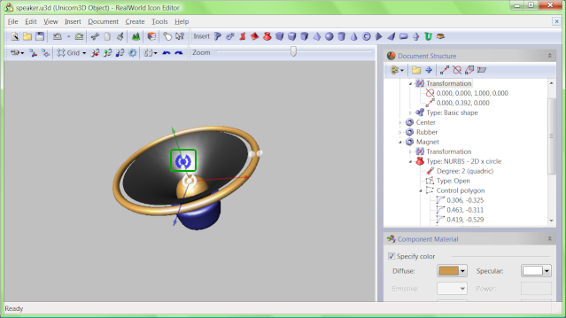 The position of the speaker edge is wrong and needs to be fixed. We will move it up by applying a translation. |
Finally, fix the position of the speaker's edge by moving it up. Expand the Transformation node of the first component and modify the second number in the second sub-item or use the transformation control point  . (Lock X and Z coordinates in the toolbar though.)
The 3D model of speaker is complete. Save it before continuing.
The goal of this step is to create conditions for converting the 3D model to an image and then to an icon. We will set camera position and direction, create lights, set properties of rendering device and attributes of the resulting image. These settings will be saved in a separate file.
Use right mouse button to rotate the object in lower 3D view to change camera position. If you want the exact angle as in our speaker icon, enter the values in the tree view manually under the Camera properties item.
Right click on 'Lights' item in the tree view and add an additional directional light. Finally, set properties of these lights to match the lights on the left screenshot. You may use the control points to set light directions.
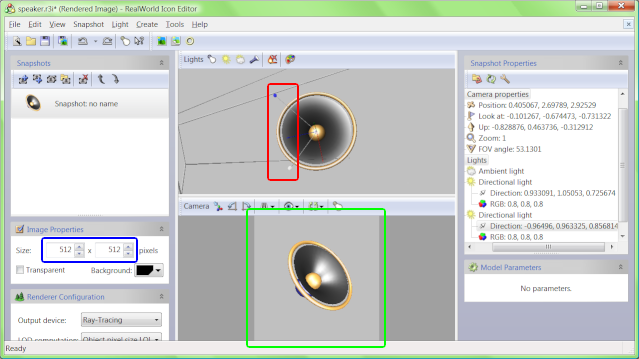 After the lights are added, some of their properties are controlled by control points in 3D view. Others are only configured from tree view. | 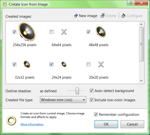 Finally click Create icon button and then select the image formats to put into your .ico file. |
The icon is generated from an image. If this image is big enough, the generated icon has smooth edges. Change the size of image from 256x256 to 512x512 to improve the icon's quality. Then click the 'Create Icon' button in toolbar or in 'Create' menu. Click OK twice and your icon is complete.
The icon was generated, the only thing left is to save it.
Creating icons from 3D models has both pros and cons. At this point, you should be well aware of them. The biggest con is the fact, that it requires more knowledge and experience than the other methods. It takes some practicing until you are able to create a 3D model suitable for an icon.
On the other hand, there are many positives. Icons look realistic and it is easy to change lighting, camera, colors or shapes. The flexibility is the key issue here. Your work is not lost if you decide, you would like to look on the object from another angle.
Another important issue for professional designers is the fact, that all icons have similar, non-obtrusive style and are suitable for long-term usage.
 Recent commentsAnonymous
on October 26th 2010
0
Recent commentsAnonymous
on October 26th 2010
0
Thanks
Anonymous
on December 9th 2010
0
how can I make a hole in a volume ?
Anonymous
on December 17th 2010
0
good
Fireguns
on March 26th 2011
0
No video! 😞
Anonymous
on August 10th 2011
0
Thanks for this tutorial ! it's good job!
😊 I would like learn more with this program!
It's not easy now , I m french !
😁
Anonymous
on November 5th 2011
0
this is really good website.....
Anonymous
on March 6th 2012
0
as do a xursor?
😁
Anonymous
on May 16th 2012
0
nice...........
😉
Anonymous
on June 15th 2021
0
I AM HERE AFTER 9 YEARS
Anonymous
on July 10th 2023
0
bro 😞
 reddit
 Facebook share