 Sign in
 Anonymous
on October 11th 2009
0
Anonymous
on October 11th 2009
0
my icon please
 | How to create a Vista-styled star icon?February 14th 2007 |
This is tutorial teaches you how to create a star-shaped icon with Windows Vista formats in RealWorld Icon Editor. The tutorial makes use of parameterized 3D models and references to components (new features introduced in version 2006.2) and demonstrates them on simple examples.
This guide is intended for people with basic knowledge about RealWorld Icon Editor. You should also know the basic technical information about icons and about icons in Windows Vista.
The following picture shows five example icons created from a single parameterized 3D model by just selecting different values for parameters. All other settings (camera, lights, renderer) remained the same.

If you follow the steps exactly, you will create these icons (and more).
Star is a very simple symmetric shape. We will create a corner of a start only once and then reference it four times. Let's get started:
 and select Symmetric surface in U direction from context menu. The shape we are trying to create is symmetric and we will use of this property to simplify the task.
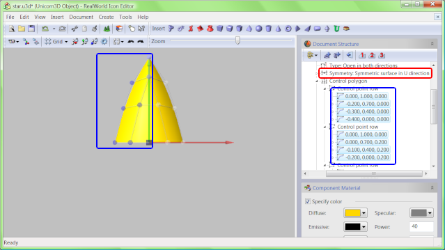
Insert a rectangular surface, enable symmetry and move the control points.
Position control points in 3D space with the help of a 3D grid. Set grid to 0.1 units (from toolbar) and position the control points  according to the screenshot above. Note that the surface remains symmetrical. You may need to rotate the model (using right mouse button) to set Z coordinates for the inner points. Alternatively, you may use the Transform Points operation from toolbar, or overwrite the coordinates in the tree view (Document Structure panel).
Referencing a component creates a duplicate, but all changes made to the original component are also visible on the duplicate. We will create four references to the previously created component.
Right-click on the name of the inserted component (it is called "Unnamed Component" by default - consider giving it a better name) and click on Create reference to component from context menu. Repeat it three more times to create four total references.
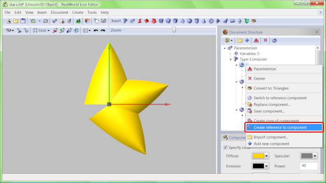
References are easily created from a component's context menu.
Find the "Transformation" items of the four new components and modify their rotation angles in the tree view to 72, 144, -144 and -72 degrees respectively (360/5 = 72 degrees).
How to do it: Each component has an associated transformation that can be used to position it in 3D space. The final transformation can consist of up to 16 simple transformations (translations, rotations, scales, and shears). By default, each component has a rotation and a translation (these two can be controlled by control points from 3D view). The rotation transformation has four numbers: the first three define direction of rotation axis, the fourth one is a rotation angle in range -180 to 180 degrees.
In our case: Since the rotation axis is by default parallel to Z axis, it is enough to set the angle. You can do it, by selecting the rotation item and by typing ",,,72" and hitting Enter. The three commas indicate that the first 3 number will not be changed.
A "How to make a star" tutorial could end here, because the star is ready and conversion to icon is a trivial task in RealWorld Icon Editor (save file, click "Render to Image", then "Create Icon", twice OK and you are done). But adding parameters to the 3D model will make it much more flexible...
In this tutorial, we will add five parameters at once. In reality, you will most likely add the parameters to your models one by one when the need arises.
 Set subtype of 'diffuse' and 'specular' parameters from context menu. |  Parameters can be also added/removed from toolbar. |
The final step is to replace selected constants with expressions. To parameterize a number right-click on an item and select "Parameterize n-th number" from context menu. A new item appears under the parameterized item and that item accepts expressions instead of constant values. Number 1-4 on the item's icon indicated which of the parent's number is controlled by that expression.
The parameterized 3D model is finished - save it as "star.u3d". If you have skipped some of the steps, you can download reference star.u3d at the and of this article. It will be needed in the next step.
Click "Convert to image" command in "Create" menu or in toolbar. A new window appears. This window allows you to define snapshots with selected parameters, light, camera positions, etc.
When creating icons with 256x256 image (e.g. Vista icons), it is recommended to increase the size of the rendered image to 1024x1024 pixels or more. Larger images will produce smoother, non-pixelated icons, but the rendering time will be longer.
Set whatever parameter values you like and then click Create icon from snapshot command from Create menu or toolbar.
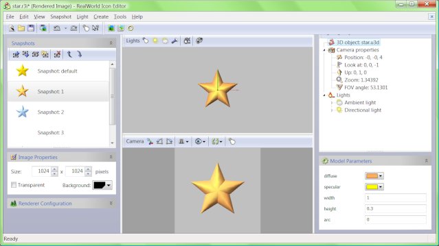
Set parameters using the "Model Parameters" panel in the lower right corner.
Click OK twice (modify the values in the dialogs if you like) and your new icon opens in a new window. You may also add a projected shadow to your icon using the appropriate drawing tool. Once you are happy with your icon, just save it and close the window...and create many more using different parameters!
![]()
![]()
![]()
![]()
![]()
An example star icon in all standard resolutions.
This tutorial demonstrated the power of parameterized 3D models on a very simple example. Parameters allow designers to fine-tune icons more quickly, reuse 3D models more easily in multiple projects or even create simple animations.
 Recent commentsAnonymous
on October 11th 2009
0
Recent commentsAnonymous
on October 11th 2009
0
my icon please
Anonymous
on March 26th 2010
0
LOVVVEEEEEEEEEEE ITTTTTTTTTTTTT :D:D:D:D:D:D:D
Anonymous
on February 26th 2011
0
Too many directions!!!!!!1 😮 😮 😮 😮 😮
Anonymous
on June 7th 2011
0
I want to make a splash for my own software but i dont want it in rectangle or square.
I want to make it any other shape like round or stars or traingle.
If anyone know how can i make splash as i want thn plzzzzzzzz help me 😞
my id is :
nenudj@gmail.com
Anonymous
on November 4th 2011
0
I work with 3D animations a lot, but I can say one thing:
DO IT PIXEL BY PIXEL NO MORE OF THIS PRESET STUFF PLEASE 😁
Anonymous
on August 30th 2012
0
best beauty wooooooooooooooow love nice
i love drawer
i love creator
😎
MyraLuvCat
on November 21st 2012
0
![]() i luv it
i luv it
Anonymous
on September 12th 2013
0
I came here looking for something simple. What I found is a program which is both complex and time consuming. There are simple programs out there which will convert any jpg etc. to a windows icon in a heartbeat - and that is all I need. After some quick research, 'Folder Changer' appears to do the job. Have a great day!
Roman 😉
How do you create polygonal shapes such as a perfect pentagon, hexagon, heptagon, octagon, nonagon and decagon?

 reddit
 Facebook share