Possible future: Layer stack
Published by Vlasta on July 27th 2013.
In the past, I only blogged about new software feature that were already complete, just waiting to be published in an upcoming version. I kept my wilder ideas to myself, because I did not want to raise false expectation.
I want to break this habit and publish one of these wilder ideas today. I cannot help myself, but warn you that this is really just an idea at this point, nothing more. Your opinions are welcome.
About layers and numbers
I am going to assume, you know what layers in an image editor are good for. People usually grasp the concept of layers quite fast, because the name "layers" is well chosen and people can visualize them as a series of transparencies laying on each other (although this mental model is not very accurate, it does a good job). If you are not familiar with layers, watch a youtube video, visit wikipedia and get some practice using them.
But what is really happening under the hood of an image editor? The computer must somehow combine the content of multiple images and produce a single image (that you can see on the screen or save for web - an image without layers). The process is similar to evaluating an algebraic expression.
17 + 3 + 6 => 26
Here the numbers 7, 13, and 6 represent the layers and the number 26 is the final image. The + sign does its magic and produces one number out of two. Layered images have their own + sign, an operation that combines the content of two images and produces a single resulting image.
Let's look at another expression:
17 - 3 + 6
Here we have another operator. The - sign can also combine two numbers and produces one, but a different one than the + operator would produce. Similarly in layered images. There are not just two, but usually more than a dozen of various operators, which are called blending modes (normal, multiply, screen, difference, and many more).
How would we evaluate the above expression? In the school, they teach as to do it like this:
17 - 3 + 6 => 14 + 6 => 20
First, we have applied the leftmost - operator and in the second step, the (now also leftmost) + operator. If we did it the the other way around, the result would not be the same (8). The - sign is tricky and produces different result when the numbers around it are swapped. In the school, they say that the - sign is not commutative. In a longer expression, the order in which we apply the operators is significant.
Many of the blending modes used in layered images are not commutative either. For example the default blending mode is not commutative, which means that if you swap two neighbor layers, the result may not be the same. This may seem obvious, but it is useful to actually say it out loud, because there are exceptions. For example the screen or multiply blending modes are commutative and the result will be the same if you swap the layers. This is counter-intuitive, because our mental model of the layered image - a stack of transparencies - only has a single blending mode and always behaves in the same way.
Let's get back to the order of operations. Why have we applied the leftmost operator first? That is actually just an arbitrary decision (why most of us read text from left to right?). Because the order matters, we must all follow the same rules if we are to get the same result. From now on, we will use parentheses to explicitly indicate the order of operations and not rely on such ad-hoc rules.
(17 - 3) + 6
At this point, I would like to abandon the algebraic expressions and replace them with "image expressions". Like this:
(LAYER1 [normal_blend] LAYER2) [screen] LAYER3
The above expression represents a layered image with 3 layers (named LAYER1, LAYER2, LAYER3). LAYER1 is at the bottom. Above it lays LAYER2 and they are combined using the normal blending mode. The topmost layer - LAYER3 - is combined with the previous result using the screen blending mode.
Perhaps I could draw a crude graph representing the same arrangement of layers:
   ^
   |
[screen] <-- LAYER3
   ^
   |
[normal_blend] <-- LAYER2
   ^
   |
LAYER1
In this graph, the arrows represent the flow of data. LAYER1, 2 and 3 are sources of data and have zero inputs and one output (1 arrow pointing out of them). The blending modes are binary operators, which means that they have 2 inputs (arrows pointing in) and 1 output (arrow pointing out). The graph has one unconnected output at the top, which indicates that a single image is produced.
Layer opacity & styles
More advanced image editors offer things called layer styles. What would a layer style look like in our notation? We will see in a moment, but first let's get back to algebraic expressions:
(17 - sin(3)) + 6 => (17 - 0.523) + 6 => 17.523 + 6 => 23.523
Here, we have applied the function sin to the number 3 and the function gave us back another number. After that, the evaluation continued as usual.
For image expressions, we can adopt similar approach and designate the function BEVEL to represent a layer style that does beveling.
(LAYER1 [normal_blend] BEVEL(LAYER2)) [screen] LAYER3
Redrawn as a graph:
   ^
   |
[screen] <-- LAYER3
   ^
   |
[normal_blend] <-- BEVEL <-- LAYER2
   ^
   |
LAYER1
In this case, we have a layer style applied to LAYER2.
The BEVEL style is an unary operator. That means, it has one input (arrow pointing in) and one output (arrow pointing out). This feels natural as we intuitively know that we give bevel one image and it gives us back a modified image.
Things are getting a bit more complicated now, sorry for that. This may be a good time to grab a cup of your favorite beverage, start an image editor and do a few experiments with blending modes and style to see how they interact.
Back already? OK.
Many image editors have a layer transparency setting. At this point you should be able to write an image expression or draw a graph containing a layer with transparency setting yourself.
If transparency were modified on for example LAYER3, it would look like:
(LAYER1 [normal_blend] BEVEL(LAYER2)) [screen] TRANSPARENCY(LAYER3)
That's right. From a structural point of view, layer transparency is equivalent to a layer style. It takes one image and gives one (more transparent) image back.
Styles in RealWorld Paint
What if the layer style we are applying is more complex? What if we want to use gradient, bevel and shadow all together? In current RWPaint, each image effect can be considered an unary operator. So, we must take the functions called BEVEL(image), SHADOW(image) and GRADIENT_FILL(image) and combine them properly.
Using the same example as before, applying the style on LAYER2:
(LAYER1 [normal_blend] SHADOW(BEVEL(GRADIENT_FILL(LAYER2)))) [screen] LAYER3
In a graph form, it would look like this:
   ^
   |
[screen] <-- LAYER3
   ^
   |
[normal_blend] <-- SHADOW <-- BEVEL <-- GRADIENT_FILL <-- LAYER2
   ^
   |
LAYER1
Why have we applied the effects in this particular order? What happens if we change the order? The result will be different and sometimes not very useful. Try it yourself in RWPaint.
(BTW Photoshop smart objects work similarly as RWPaint's styles, but RWPaint has none of Photoshop's limitations associated with smart objects.)
Style in Photoshop
Photoshop approaches the problem of complex layer styles quite differently. There are no separate graph nodes like BEVEL or SHADOW under users' control. Instead, there is just one very complex node (let's call it MEGASTYLE) that has a lot of options and contains an embedded graph. It also handles the transparency setting and Photoshop's specialty - the fill setting.
   ^
   |
[screen] <-- LAYER3
   ^
   |
[normal_blend] <-- MEGASTYLE <-- LAYER2
   ^
   |
LAYER1
The following graph represents the internal working of the MEGASTYLE operator if it is configured to do gradient fill, bevel and shadow. This was simplified, the reality is a bit more complex, different blending modes are used internally and bevel is actually split into two blending steps for light and shadows. Transparency and fill are also part of the real graph.
   ^
   |
[normal_blend] <-- SHADOW <----------+
   ^                                 |
   |                                 |
[normal_blend] <-- BEVEL <---------  |
   ^                              |  |
   |                              |  |
[normal_blend] <-- GRADIENT_FILL  |  |
   ^                 ^            |  |
   |                 |            |  |
   +-----------------+------------+--+
   |
The graph above has one input and one output, because, remember, this is the MEGASTYLE unary operator, which takes one image and gives back another image. As you can see, the structure of this operator is hard-coded and you cannot change the order of the individual steps. This has both advantages and drawbacks (you cannot shoot yourself in the foot be putting shadow before bevel, but you cannot for example use 2 bevels in your style, which is sometimes useful).
The adjustment layers
Photoshop also supports the so called adjustment layers. An adjustment layer is also an unary operator, much like a normal layer style. But it is placed in a different position in the graph (or expression).
ADJUST(LAYER1 [normal_blend] LAYER2) [screen] LAYER3
The expression above has 3 normal layers and 1 adjustment layer. The adjustment layer is placed between LAYER2 and LAYER3. As it should be obvious from the expression, the adjustment is applied to the result of LAYER1 and LAYER2. Here is a graph:
   ^
   |
[screen] <-- LAYER3
   ^
   |
ADJUST
   ^
   |
[normal_blend] <-- LAYER2
   ^
   |
LAYER1
Layer masks
Imagine our original example, but with a layer mask on LAYER2. Here is a graph:
   ^
   |
[screen] <-- LAYER3
   ^
   |
ADJUST
   ^
   |
[normal_blend] <-- [masking_op] <-- LAYER2_MASK
   ^                   ^
   |                   |
   |                LAYER2
   |
LAYER1
[masking_op] has - like a blending mode - two inputs (layer content and layer mask) and one output. It is essentially a blending mode, but as you can see, it is placed in a different position in the graph than normal blending modes are allowed to be.
Problems of layers
At this point, we can stop analyzing individual properties of the layers concept and focus on its weaker points.
No hierarchy
With algebraic expression, you can do this:
(17 - 3) - (6 + 2)
But you cannot do the same with layered images. The following image expression cannot be transformed to a list of layers:
(LAYER1 [normal_blend] LAYER2) [screen] (LAYER3 [normal_blend] LAYER4)
While it may appear that Photoshop allows you to do the above with layer groups, it really does not. Layer groups are not functional groups, they are only visual tool that improves presentation of data in the user interface. If you create 2 layer groups with 2 layers in each group, Photoshop does this (it ignores the groups):
((LAYER1 [normal_blend] LAYER2) [screen] LAYER3) [normal_blend] LAYER4
Depending on the actual content of the layers, the result could be different.
Why is hierarchy important? It allows you to split a large task into several smaller ones. Imagine you are drawing a face and you create layer for mouth, eyes, nose, hair, etc. And then you realize you actually need several layers just for eyes. You want these eyes layers isolated from they rest, but it is impossible. They will interact with all of the other layers in your image. Layer masks actually exist just to remedy this problem of isolation (and not in a very good way). If Photoshop supported true hierarchy, layer masks would not be needed, because they could be normal layers with the [masking_op] as their blending mode.
No reuse
Each layer can only be used once in a layered image. If you need to use the same layer multiple times, it must be duplicated. A duplicated layer is suboptimal, because the copies take up more space and a modification made to one of the layer must be manually copied to the duplicated layer(s).
Consider for example the Orton effect:
(LAYER1 [multiply] LAYER1) [screen] BLUR(LAYER1 [multiply] LAYER1)
This expression uses the same image 4 times. It cannot be non-destructively (as a style) created in Photoshop.
Inflexible graph structure
Layer styles (unary operators) are only allowed in certain places in the graph. Imagine for example that you would want to replicate the infamous glass effect from the Windows Aero style. This effect blurs content under semitransparent regions. One of the steps involved in the Aero effect blurs all content under the selected layer and then puts the blurred content under semitransparent regions of a window.
Its graph may look like this (LAYER1 is desktop background, LAYER2 contains window content):
   ^
   |
[normal_blend] <-- SHADOW <--+
   ^                         |
   |                         |
[image_switch] <-------------+-- LAYER2
   ^      ^
   |      |
   |     BLUR
   |      ^
   |      |
   +------+
   |
LAYER1
What we see here is a ternary operator (it has a 3 arrows pointing to it) called image_switch. This operator selects one of the two primary input images depending on the third input. This kind of structure (ternary operator) is impossible to express using classic layers.
It is possible to place this whole graph into a single box and call it a new blending mode. But that is not the point. Such a blending mode would have to be created by software authors, while layers and styles are created freely by software users. Blending modes also cannot have any configuration. Have you noticed how the number of blending modes in Photoshop is continually raising and normal users are already having problems understanding them? This structural inflexibility is the reason behind it.
Enter the Layer stack
Despite the mentioned problems, layers are a very successful and powerful concept. Maybe they really are the ideal mix of simplicity and power. Any concept that should eventually replace layers must not neglect a learning curve associated with it.
On the other hand, over the years, too many workarounds were introduced. Despite layer styles, adjustment layers, layer masks, clipping masks, transparency and fill settings, there are still cases that are impossible or annoying to do with layers. Also, the addition of all these special workarounds have made mastering of layers quite difficult. Maybe it is time to start over with a more powerful concept with few hard rules and no exceptions.
Graphs like the ones shown above are capable of expressing all kinds of structures, but it will be very hard for occasional users to understand and use them. That would not be the right approach for a general purpose image editor.
Clearly, the replacement for layers must look similarly to layers, at least in simple situations. Here is my proposal:
[screen]
LAYER3
[normal_blend]
BEVEL
LAYER2
LAYER1
From far away, this look just like layers (list of item arranged vertically). If you look more closely, you will see that some of the items are not actually layers, but layer styles or blending modes. All these different items are just mixed together. This seems like a mess. How can one put layers, blending modes and layer styles on one heap and expect to get a sensible result?
Well, if you write "5 + 3", you have also put different things (operators and numbers) together and you still know how to work with it. Because you know the underlying rules. And now I am going to tell you how to evaluate the above mess. (BTW it actually is a program in an incomplete concatenative language, but don't be alarmed, you do not need to be a programmer to understand it.)
We will start evaluating this program from the bottom, just like we do with layers.
- The first item there is LAYER1 - we put it on the stack. A stack is a handy place, where we can put things we do not need at the moment.
- The second item is LAYER2 - we put it on the stack as well. (LAYER 2 is now on the top of the stack and LAYER1 is below it.)
- BEVEL is the 3rd item. It actually requires one image to work properly and so we grab one item (LAYER2) from the top of the stack and apply BEVEL on it. We put the result back on the stack. The stack now contains beveled LAYER2 and underneath is saved LAYER1.
- Now comes [normal_blend]. This is a blending operation that requires 2 images to work properly. Fortunately, we have 2 images on the stack and so we take them from the stack and run the normal blending operation. Then we put the result back on the stack. Now, we only have this one item on the stack.
- What shall we do with LAYER3? Let's put it on the stack.
- Finally, we process [screen]. This is a blending operation that takes 2 items from the stack and places the result back on the stack.
The evaluation is complete and we are left with a single item on the stack. This item represents the final image. Neat, but not groundbreaking. We could do the same with classic layers.
At this point you know all the rules you will ever going to need to understand these "layer stacks". Each line takes its inputs from the stack and puts its outputs back on the stack. You also need to know the "obvious" things we have mentioned before while drawing the graphs. Like that layers have no input, blending mode needs two image to blend them together. Bevel needs one image to apply bevel to, etc. All these things should be obvious.
In trivial cases, the layer stack will be very similar to classic layers.
[blending_modeN]
LAYERN
...
[blending_mode3]
LAYER3
[blending_mode2]
LAYER2
LAYER1
The only difference is that LAYER1 has no blending mode (because there is nothing to blends it with).
Unleashing the layer stack
So, Now I am going to show you how to do all the stuff you could do with layers and more.
What if we wanted to apply bevel on the combination of LAYER1 and LAYER2. That would be an equivalent of an adjustment layer doing bevel (which you cannot actually do in Photoshop, but anyway, replace BEVEL with ADJUST if you want to). Here is how it would look like:
[screen]
LAYER3
BEVEL
[normal_blend]
LAYER2
LAYER1
By merely swapping the BEVEL and [normal_blend] lines, we have managed to turn a layer style into an adjustment layer.
What if we instead wanted to first blend beveled LAYER2 with LAYER3 using the screen blending mode and only then blend it above LAYER1 using normal blending mode. Here it is:
[normal_blend]
[screen]
LAYER3
BEVEL
LAYER2
LAYER1
Again, we have managed to change the order of the processing by changing the order of the items. We have just built a hierarchy. This is actually something that was impossible to do with layers.
Let's try another thing: the Orton effect mentioned above. To be able to do it, we will need a new thing. It is called DUPLICATE, takes 1 input and produces 2 outputs. It simply duplicates the item on the top of the stack. And here is the Orton effect:
[screen]
BLUR
DUPLICATE
[multiply]
DUPLICATE
LAYER1
The nice thing about this is that LAYER1 is there only once. This is actually an image with a single layer. The rest can be considered a fancy layer style.
And finally, we will attempt to do the Aero Glass effect. Unfortunately, we will need one more operator for this. The ROTATE_N operator rotates N items on the stack. For N=2, it just swaps the top 2 items. For N=3, the top item is placed 2 spots lower and items on these two spots will raise up. And here is how the Glass effect looks like:
[normal_blend]
SHADOW
ROTATE_2
[image_switch]
ROTATE_4
DUPLICATE
LAYER2
BLUR
DUPLICATE
LAYER1
I admit that it does not look great, you may need some practice before you'll be able to design these things. An it may look even worse, for example like this:
[normal_blend]
SHADOW
ROTATE_2
[image_switch]
ROTATE_3
ROTATE_3
BLUR
DUPLICATE
ROTATE_3
ROTATE_3
DUPLICATE
LAYER2
LAYER1
Why have I made the complicated thing even more complicated? If you look closely, you will notice that the actual layers are at the bottom. And all the complexity of the Glass blending mode resides above them. What if we could just take all these ugly items and put them in a nice little box? A nice little box with a label [glass]? Then the whole thing could look just like:
[glass]
LAYER2
LAYER1
The [glass] becomes a user-defined operator, much like a user defined layer style you can use in Photoshop or RealWorld Paint today. Except much more flexible.
I could continue giving more examples of what would be possible with layer stack, but I think I have made the point. Layer stack is more powerful than layers and the simple case (just a list of layers) is almost as simple as with layers (depending on the user interface of the software).
User interface
That is always the most difficult part of software design. Here, I have tried to draw a mockup screen of a real case. The image on the screenshot has 4 layers and some layer styles.
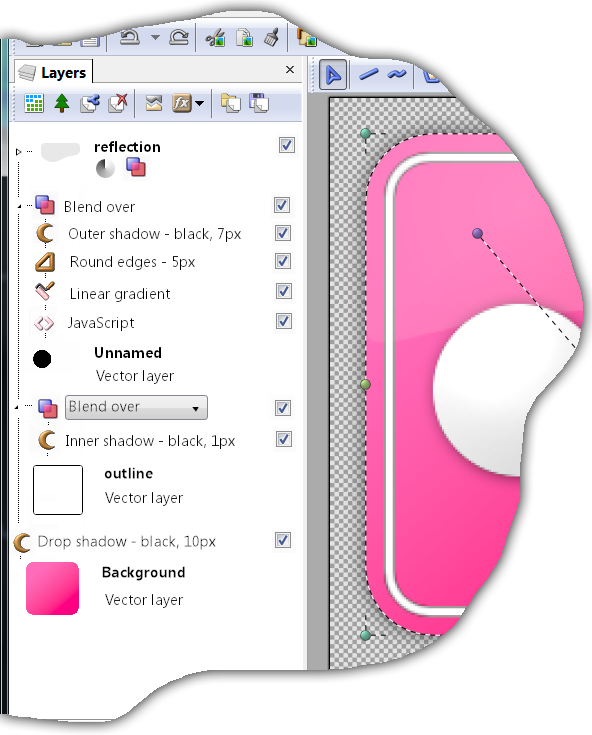
You can read this from bottom to top, because it is a valid layer stack program. But there are some bells and whistles to help users navigate. The dotted lines show flow of data. The top layer is collapsed and only icons of the operations within it are shown. The 2 layers below it are expanded and you can see all details - layer style components and blending mode (the name layer style is actually obsolete in this case). There are checkboxes that can be used to temporary turn off individual parts.
The great thing about this is that if I did not tell you about the "layer stack", you would probably think that this is just an ordinary layered image, only with effects and blending modes displayed explicitly in the list of layers. And that was the goal, if the user does not want anything more than what layers offer, it should not be more complicated. But the hidden power is there, just waiting for the right moment.
So, what do you think? Would a layer stack be worth spending a year of development time on?
All the used concepts are already being used in software today, also in software related to computer graphics. But they are usually not presented directly to the end user in a graphical user interface. PostScript is a stack-based language and a complete one. It is difficult to learn for normal users and it is difficult to present it in a form better than plain text. Layer stack is supposed to be half way between classic layers and PostScript. Still powerful enough to cover many interesting scenarios and simple enough for newbies to quickly learn the basics and be productive. Simplicity also makes it possible to present the data in better than plain text format (as seen on the image above).
One more thing. I realize that the term "layer stack" is pretty bad. If anyone can suggest a better way to call this image designing concept, I am all ears. Hint, the "layer" word should be there to make people comfortable.
 Recent comments
 Anonymous
on July 31st 2013
0
Anonymous
on July 31st 2013
0
It's an intriguing concept, but I think it would be appreciated if you could have both stacks and classic layers, for it's simplicity for newbies....hmm...what if you made the "stacks" info in a "layer properties" window? Don't get me wrong it's really powerful and awesome, but overwhelmingly complex if you don't know what you're doing.
lo siento, estoy un poco mareado con este
Es mejor usar el modo clásico 😴
Very interesting post, I think it is a powerful idea. Perhaps it could be named the layer outline, or go with an alliteration and dub it the document dashboard. These names aren't too descriptive but the average user need not be troubled by the details.
 Sign in
 Tweet
Tweet Share
Share